 Home
Home Blog
Blog New
New Site Map
 Music
Music Sailing
 Climbing
 Running
 KLL
KLL Web
WebSorry to make this page such a hefty download, but it contains over thirty photographs and at least you can start reading the text (NB I was still on 56K dial-up when I uploaded it so I know how it feels!) while they’re filling up their place-holders...
When David Thomas designed the Impala for Hunter Boats in 1977, he drew a clever outboard well (subsequently copied for other Hunter designs) where the permanently mounted engine can be lifted clear of the water and swung back into its own locker with the necessary hull opening faired off with a blanking plate. And, when the class rules were later modified to permit an inboard alternative, the same designer drew up an installation so neat and accessible that it is widely believed to have been in his mind all along.
While most racing classes and handicap systems would offer some time allowance to a boat converted from outboard to inboard engine (if such a thing was permissible at all), the Impala 28 Class Rules (and all ratings derived from them that I’m aware of) are perhaps unique in offering true one-design (level rating) racing for both outboard and inboard boats by requiring the outboard boat to carry extra weight to compensate for the drag of the inboard model’s stern gear.
When I bought Fly in November 1998, she was an outboard Impala (powered by an 8hp Mariner 2-stroke) and remained so throughout the 1999, 2000 and 2001 seasons. But the 2-stroke, being both uneconomical and frequently forced to ‘inhale’ its own smoke in the well, proved to be frustrating for cruising and regular regatta deliveries. So I could simply have bought a 4-stroke outboard but, clever as the Hunter outboard system is, preferred to fit the alternative Yanmar 1GM10 inboard diesel.
Now, the pros and cons of inboard and outboard Impalas have been keenly debated for years, so I’m quite prepared to refer interested readers to this discussion from our class forum [2018 edit: or would if it still existed] for a range of opinions. To summarise the arguments as I see them, however:
An outboard is relatively cheap to replace, can be swapped for another if it goes wrong, leaves a theoretically flush bottom to the hull and probably suits a racing Impala with limited need to motor. But 2-stroke installations suffer from poor fuel economy, lack of range, noise and the self-choking tendency mentioned above, and all Impala outboard installations from the need to fit and remove the blanking plate when racing and the needless quantity of water sucked into the well when sailing fast.
The inboard is economical, offers a greater range (no more wild goose chases with the petrol cans!) and is certainly quieter than a 2-stroke. It releases a useful stern locker where the outboard was, but still preserves much of the useable space under the cockpit where the stern gear goes, and allows a lighter Impala because of the compensatory weight required by the outboard boat. While it costs more to install and can’t just be swapped at the drop of a hat, the lighter weight of the inboard boat and loss of the well (which can never in my opinion be sealed well enough to completely eliminate drag) strike me as a fair trade-off for the two feet of shaft and folding prop sticking out of the bottom.
To highlight one slight anomaly of the weight differential, however, I must add that the specified minimum weights for inboard (2410kg) and outboard (2520kg) boats aren’t strictly comparable because replacing 160kg of ballast and 28kg of outboard with 76kg of inboard leaves a mere 2kg over the notional 110kg difference for shaft, P-bracket, prop, bearers and quite a lot else. So it’s basically not possible to convert a minimum weight outboard Impala into a minimum weight inboard Impala (although you might get close) unless you can find some further weight to lose!
To make one thing clear from the start, the key factor in Fly’s successful inboard installation was the considerable expertise of my good friend Twig Olsen, but much willing assistance was certainly provided over the course of many weekends by his son Alistair and myself. The copy of David Thomas’s detailed installation drawings that we used was borrowed from fellow Impala owner Stuart Higgins, to whom I am also grateful.
While Twig’s original suggestion was to look for a suitable second-hand Yanmar 1GM10, that idea was soon discarded in favour of a good deal on a new one, which I collected from Glasgow in due course. So Twig towed Fly down to his base at Lorn Sawmills, where we kept her under cover from February to May 2002, and down to work we got.
If some aspects of the process are described here in greater detail than others (and some not at all), this is because the description takes the form of a photo commentary based largely on various emails, forum postings and other notes collated retrospectively. So, while I might or might not be able to answer further questions, I’m certainly willing to try.
Many of the photographs were taken by Twig, but some of them are mine and all of them are copyright to one or the other of us. The thumbnails link to 512x384 versions of between 27 and 51K.
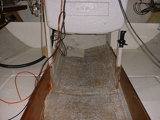


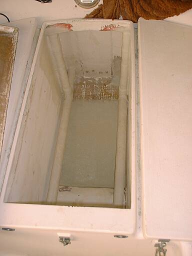
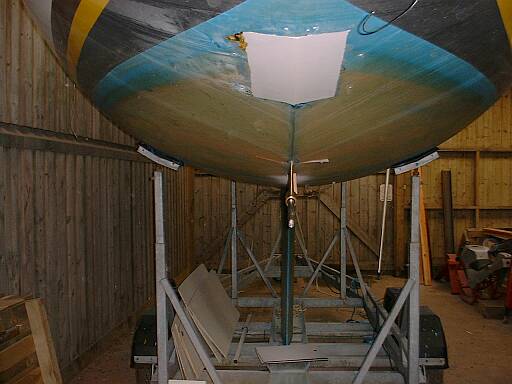
The first big job was removing the extra ballast and stripping the old paint from the bilge to ensure the best bonding surfaces possible, which was hard work but worth the effort. The reel of fishing line visible above the stern tube slot in the third picture was used to set up the line for the engine bearers, stern tube and shaft, whose angle we raised from 10° to 11° to get the 2¼" prop clearance we wanted. And the piece of boat we cut out to make that slot was so solid and well-laminated that I kept it as a souvenir...
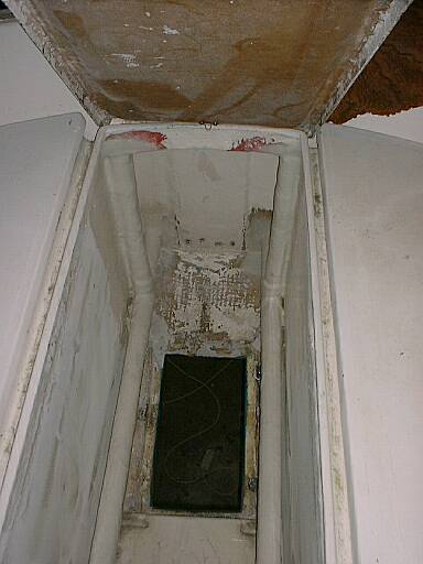
Here we departed slightly from the plans, preferring glassed-in 1½" drains with no constricting skin fittings to 2" drains with. The bushes for the old outboard lifting gear (visible at the bottom of the third photo) were subsequently reused to string rope footrests for my long legs between that bulkhead and the traveller.
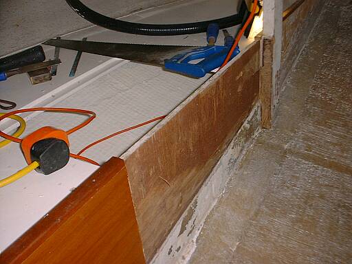
To explain what’s happening here, Fly’s starboard bunk front (which split up the galley bulkhead following a grounding incident) was doubled as part of a major repair during the winter of 1999–2000, but cut back to the original thickness aft when we installed the inboard.
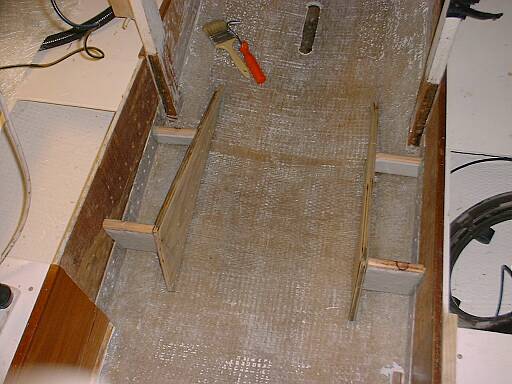


So that’s Twig at work in the second photo in case it’s hard to tell! Note the space below the side webs of the bearers to allow drainage all round.
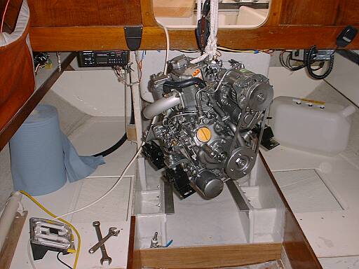
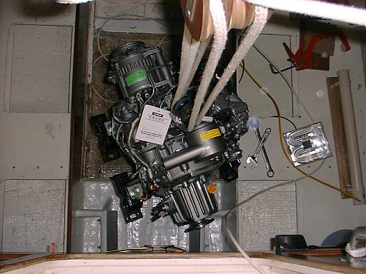
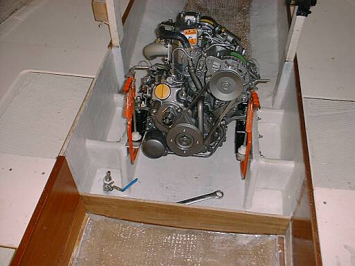
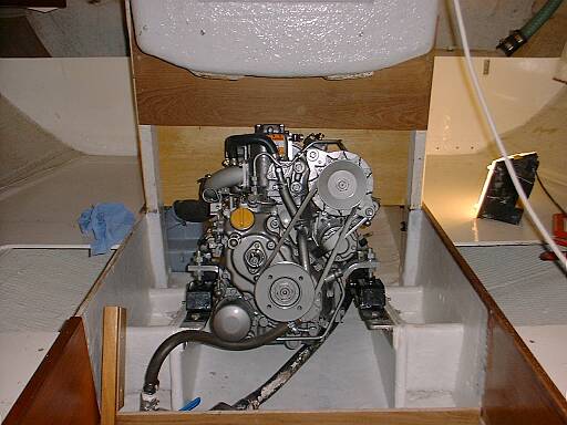
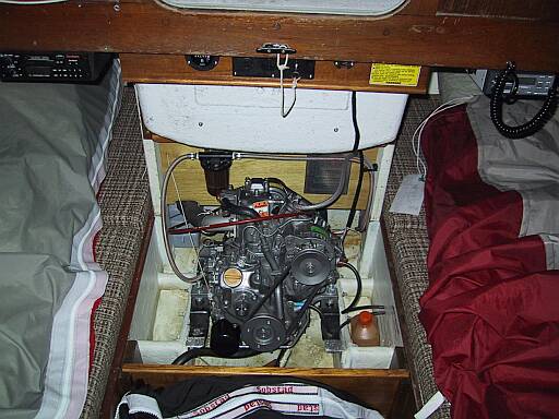
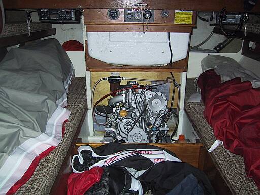
While we photographed the engine at every stage from delivery pallet to installation and beyond, these are probably the most interesting shots. A further refinement for the 2003 season (so not shown here) was to drill a series of holes up the part bulkhead obscuring the fuel tank to make a fuel gauge of sorts.

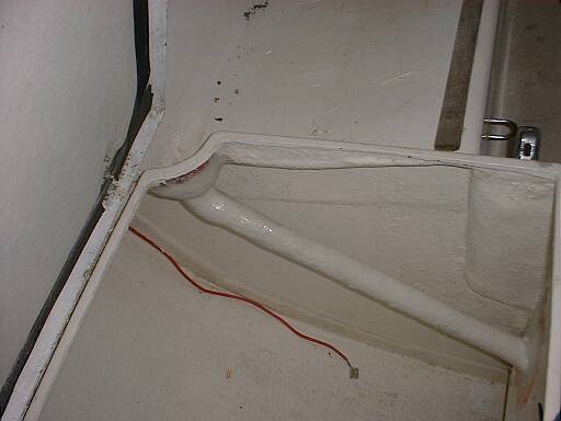
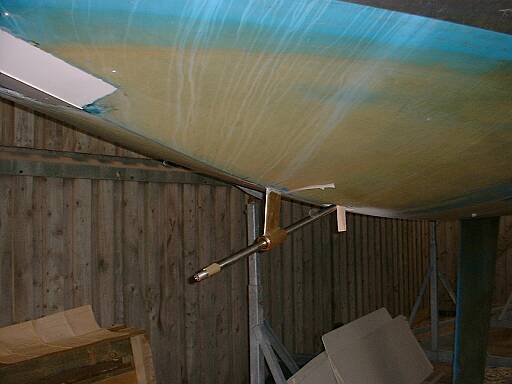
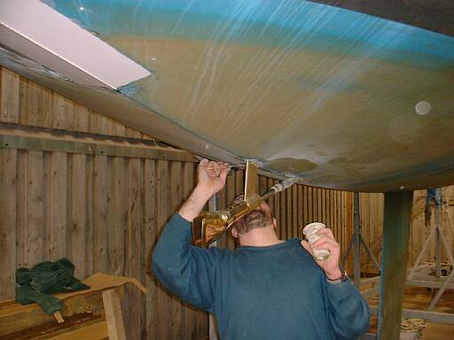
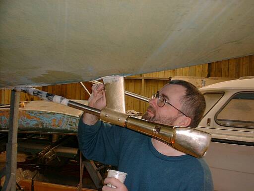
Twig’s hand glassing in the P-bracket! The stern gear is covered in use by plywood boards at bunk-top level, retaining about half of the old under-cockpit stowage space.
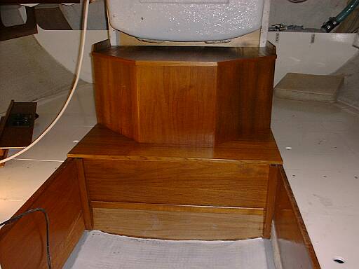
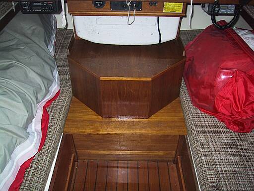
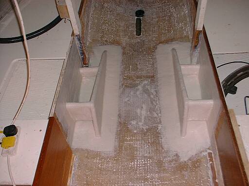
This beautiful engine box with integral steps, 45° angled front corners and separate drop-in front panel to bunk-top height was Twig’s pièce de résistance! We built it very light with plywood and epoxy, but there’s plenty of strength where it needs it...

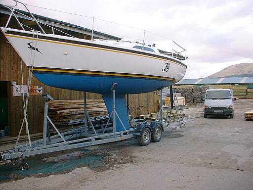

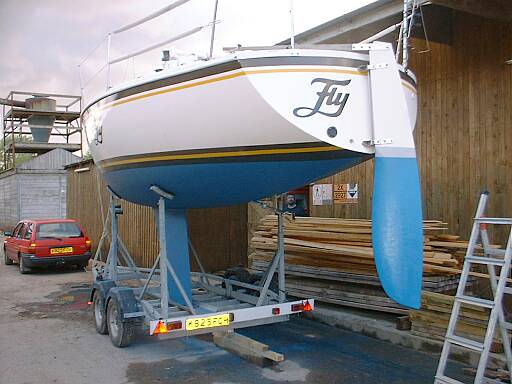
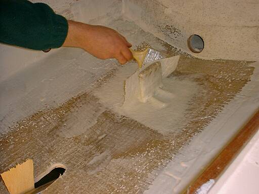
Me at work this time (when I weighed 3 stone more than I do now), fairing off some bits and pieces with Finefill. Now, it was a great idea to lay up the bottom of the former outboard well directly instead of incorporating the old blanking plate, but I was yet to discover that stripping off the antifouling from that area first would have saved me a lot of work when it came to fairing it. So, no, the Escort estate doesn’t tow the boat (just the empty trailer) and, no, the new rudder doesn’t have a grey boot topping... it’s just that these photos were taken before I’d finished the painting (‘Blue’ Peter visible through shed door in fifth photo)!
Perhaps it’s worth pointing out that all Impala plans including the inboard installation drawings show the accommodation to be offset slightly to starboard (ie with the port bunk front 13" from the centreline but its starboard equivalent 15") but the boats aren’t built like that. The shaft-drive Yanmar 1GM10 comes in a choice of three different gear ratios, of which we chose the middle at 2.62:1. A Gori 14" x 9½" prop (chosen after some discussion in preference to a 14" x 9") brings a top speed of over 6½ knots in calm conditions but still drives the boat happily when the going gets tougher. The whole project cost around £3500, of which the engine (£2291.25) and propellor (£389.51) were easily the most expensive single items, but we certainly saved money through having the necessary wood, glassfibre, resins and other oddments to hand as well as carrying out the work ourselves.
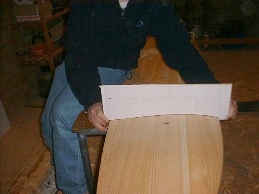
Since I’ve heard the original Impala rudder described as everything from ‘very poor’ to ‘a bit of plank’, it was perhaps inevitable that David Thomas should be asked to design a replacement, and the Mk 2 Rudder was adopted (with the old design grandfathered) for the 2000 season. While it’s not much deeper than the original, and possibly carries no more area, the new rudder benefits from a completely different shape and provides greatly improved control in previously marginal situations. It’s also a potentially expensive upgrade (costing several hundred pounds from a professional builder), but we bought the plans from the designer (£20) and built our own simultaneously with the inboard installation.
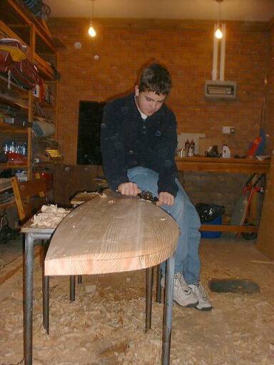
Fly’s new rudder blade was laminated fore-and-aft with strips of larch and shaped by Twig and Al before the three of us joined forces to cover it with two layers of glass cloth and epoxy. So it was smooth enough before that, but the cloth is rough, the epoxy’s hard and I spent a whole weekend sanding it with a long block before taking it home to skim and fair twice more with Finefill and wet-and-dry. The resulting blade, which is both beautiful and very, very fair, probably cost less than £100 to make but, at an estimated 40 man hours to shape and finish, was certainly not a ‘cheap’ option in terms of time!
This relatively minor, but excellent, modification was described by Trevor Pountain in the Class Forum [sorry: now defunct] and applied to Fly for the 2003 season. Sometime I might add some ‘before and after’ photos here.
Feedback to sailing@petestack.com